[Research] Windows Nonpaged Pool Overflow Exploit with HEVD (EN)
0. Overview

Hello, I’m minzu, and this is my first research article for Hackyboiz, focusing on Windows Kernel Pool and Nonpaged Pool Exploitation.
After joining Hackyboiz, my first goal was to study Windows Kernel vulnerabilities and exploitation techniques in greater depth. With SeoPPak, I started a project to build a database of Windows Kernel exploits. We studied how Windows Kernel vulnerabilities can be used to achieve EoP (Elevation of Privilege).
Among Windows vulnerabilities, I chose Pool-related vulnerabilities as my first target. One of the first things we need to understand when studying Windows Kernel Pool Exploitation is Kernel Memory Management. We need to identify which objects may be placed around a vulnerable memory object when it is accessed, and how other objects change after the vulnerability is triggered.
In this article, I will cover the Windows Kernel Pool concepts needed for our discussion, using Windows 11 25H2 (26200.9711) as the reference environment. I will then explain how to exploit the NX Nonpaged Pool Overflow vulnerability in HEVD.
1. Windows Kernel Pool Architecture
In Windows, both User Mode and Kernel Mode can allocate memory dynamically. In User Mode, the User Heap Allocator allocates memory in the user-space Heap through functions such as malloc, new, and HeapAlloc. In contrast, Kernel Drivers use APIs such as ExAllocatePool2 and ExAllocatePool3 to obtain dynamically allocated memory from the Kernel Pool through the Kernel Pool Allocator.
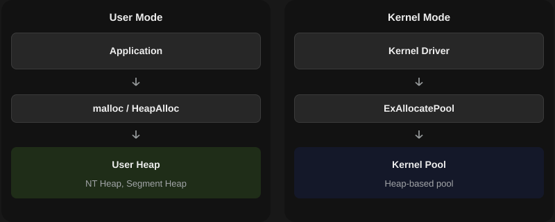
For a better understanding of Kernel Pool, it may help to read the Hackyboiz articles on NT Heap and Segment Heap, which discuss Heap allocation in User Mode.
In Kernel Mode, dynamic memory allocation is needed for objects such as buffers used by drivers to process I/O requests and file objects managed by file systems. Windows therefore provides APIs such as ExAllocatePool2 to allocate memory from the Kernel Pool.
In the Windows 7 era, the Pool Allocator managed memory primarily through Pool Descriptors, size-specific Free Lists, and structures such as _POOL_HEADER. Since Windows 10 19H1, however, Windows has used a Heap-backed Pool architecture, changing how memory blocks are managed internally.
Since Windows 10 19H1, the internal management of Windows Kernel Pool has shifted from the traditional Pool Descriptor- and Free List-based architecture to a Heap-backed Pool architecture. As a result, even when the same Pool API is used, allocation may follow different Allocator paths, including LFH (Low Fragmentation Heap), VS (Variable Size), and Segment Backend, depending on the requested size and the internal state of the Heap.
1.1 Pool Allocation API
In Kernel Mode, ExAllocatePool2 is one of the main functions used for Pool allocation.
DECLSPEC_RESTRICT PVOID ExAllocatePool2(
  POOL_FLAGS Flags,
  SIZE_T     NumberOfBytes,
  ULONG      Tag
);| Parameter | |
|---|---|
Flags |
Pool type and memory allocation attributes |
NumberOfBytes |
Number of bytes requested by the caller |
Tag |
Identifier used to track allocations |
If ExAllocatePool2 successfully allocates a Pool, it returns a pointer to the allocated memory.
First, POOL_FLAGS is a 64-bit value that describes the Pool Type. The Flags argument lets the caller request a Pool with the appropriate attributes, with various Pool types represented in those 64 bits. Second, NumberOfBytes specifies the size of the usable region provided to the caller. Because a metadata header called _POOL_HEADER precedes the Pool, the allocated Pool space consists of the size of _POOL_HEADER plus NumberOfBytes. We will examine this in more detail later. Finally, Tag is a four-byte identifier used to distinguish Pool allocations. For example, Pool allocations made for a Named Pipe use the tag NpFr.
1.2 Pool Types
① Paged Pool & Nonpaged Pool
Kernel Pool is divided into Paged Pool and Nonpaged Pool based on whether its memory must remain resident.
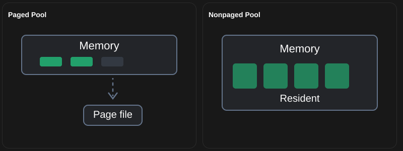
Pages in Paged Pool can be paged out of physical memory according to memory management policies. When necessary, the Memory Manager can move the contents of physical pages from RAM to disk. If a page is not currently resident in physical memory, accessing it causes a page fault, and the operating system brings the required page back into memory.
Nonpaged Pool is used by code that requires memory to remain available whenever it is accessed. It is particularly important on execution paths running at elevated IRQL, where ordinary page faults cannot be handled. Because page faults cannot be handled at high IRQL levels, data that must be accessed at DISPATCH_LEVEL needs to reside in Nonpaged Pool.
② Mitigation : NX
As on Linux, NX (No-eXecute) is a mitigation that prevents data on a page from being executed. If bit 63 of the PTE is set to 1, NX is enabled.
In Windows, ExAllocatePool2 is commonly used to request Pool allocations. Its first argument is a flag that specifies the Pool’s attributes. An allocation using POOL_FLAG_NON_PAGED requests NX Nonpaged Pool. To request Nonpaged Pool without NX mitigation, the POOL_FLAG_NON_PAGED_EXECUTE flag must be used. In other words, even for Nonpaged Pool, the caller can choose whether NX is enabled.
For example, consider allocating dynamic memory in one Pool with NX mitigation and another without it.
// NX Nonpaged Pool
PTE = 8A0000009183E963

// Executable Nonpaged Pool
PTE = 0A0000004D471963
When we inspect the PTEs of these Pool allocations in WinDbg, we can see that the most significant bit of the PTE is set to 1 only when NX is enabled.
2. HEVD Nonpaged Pool Overflow Vulnerability
2.1 Root Cause
The vulnerability examined in this exploit is BufferOverflowNonPagedPoolNx. HEVD is an intentionally vulnerable kernel driver, and this function contains code that causes an overflow in NX-enabled Nonpaged Pool.
KernelBuffer = ExAllocatePoolWithTag(
    NonPagedPoolNx,
    0x1F0,
    'kcaH'
);

ProbeForRead(UserBuffer, 0x1F0, 1);

RtlCopyMemory(
    KernelBuffer,
    UserBuffer,
    InputBufferLength
);
The vulnerability is as follows: the kernel allocates 0x1F0 bytes of Nonpaged Pool, but RtlCopyMemory uses InputBufferLength rather than the allocated buffer size of 0x1F0.
ProbeForRead checks whether a user buffer is readable within a specified range. It only verifies that the buffer can be accessed; it does not validate the size of the destination KernelBuffer. In this code, KernelBuffer is allocated with a size of 0x1F0 bytes, while RtlCopyMemory() uses the separate InputBufferLength value as the copy size. Therefore, an Overflow occurs when InputBufferLength exceeds 0x1F0.
This vulnerable kernel Pool is allocated with the tag ‘Hack’. From here on, I will use ‘Hack’ to identify the vulnerable buffer.
2.2 Flow
As mentioned earlier, not only the type of Pool being allocated but also the Allocator handling the request is important. HEVD makes its allocation through ExAllocatePoolWithTag. Because this is an older Pool allocation function, it ultimately leads to ExAllocatePool2 on modern Windows 11 systems. Examining the Pool allocation functions on recent versions of Windows reveals the following call flow.
ExAllocatePoolWithTag
    ↓
ExAllocatePool2
    ↓
ExpAllocatePoolWithTagFromNode
    ↓
ExAllocateHeapPool
    ↓
RtlpHpVsContextAllocate
Tracing the calls shows that the VS Allocator is used in the 25H2 environment.
According to the Pool-related material and the HEVD exploit reference, a Pool allocation of 0x1F0 bytes is handled by the LFH Allocator. The LFH and VS Allocators are generally distinguished around the 0x200-byte boundary. On 24H2, the allocation was handled by the LFH Allocator. On 25H2, however, allocating 0x1F0 bytes causes the BlockSize value recognized by the Pool Header to become 0x200. The Pool is therefore treated as 0x200 bytes for this purpose and allocated through the VS Allocator. Importantly, this does not mean that the dynamically allocated data region itself becomes 0x200 bytes. Rather, 0x200 is the size recognized by an internal function when selecting its allocation path. This behavior can also vary with environmental factors such as LFH bucket activation and alignment.
Accordingly, this article proceeds on the assumption that Pool allocations of this size are handled by the VS Allocator.
3. Kernel Pool Allocator Internals
So far, we have briefly covered the fundamentals of Windows Kernel Pool and its allocation APIs, along with how HEVD allocates Pool memory. To understand this process in greater detail, we need to understand the Allocator itself. Let’s briefly examine the Kernel Pool Allocator before discussing LFH and VS.
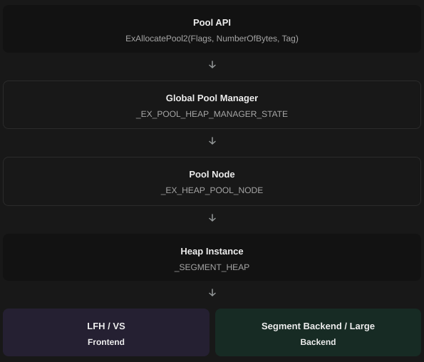
When a driver calls ExAllocatePool2, Windows must select an appropriate Pool allocation path. Some requests may use LFH slots, while others use VS Chunks. For larger allocations, the Segment Backend may obtain page ranges directly, or Windows may use a separate Large Allocation path. In this article, we will focus on VS.
3.1 Differences Between LFH and VS

LFH (Low Fragmentation Heap) manages memory belonging to the same Size Class in fixed-size Slots. For example, if the Slot size in an LFH Subsegment is 0xD0, the Slots are laid out at regular intervals.

VS (Variable Size) manages Chunks of different sizes. Because a single VS Subsegment can contain Chunks of varying sizes, the size and state of the current Chunk must be examined to determine the location of the next Chunk.
This is the most important difference between the two Allocators. To manage Chunks of different sizes, the VS Allocator stores each Chunk’s size and state in _HEAP_VS_CHUNK_HEADER. It also uses FreeChunkTree to find Free Chunks of varying sizes efficiently.
3.2 VS Structure
Management of the overall VS state begins with _HEAP_VS_CONTEXT. In Windows 11 25H2, VsContext is located at offset +0x2C0 within _SEGMENT_HEAP. VS manages its state through the structures shown below.
| Structure | |
|---|---|
_HEAP_VS_CONTEXT |
Overall VS configuration and Affinity management |
_HEAP_VS_AFFINITY_SLOT |
FreeChunkTree, SubsegmentList, Delayed Free |
_HEAP_VS_SUBSEGMENT |
Memory range containing the actual Chunks |
_HEAP_VS_CHUNK_HEADER |
Size and state of each Chunk |
_HEAP_VS_CHUNK_FREE_HEADER |
Tree management information for Free Chunks |
Using these structures, VS finds a suitable Free Chunk for a new request and, depending on the conditions, may split a larger Chunk or merge adjacent Free Chunks.
The structure most directly relevant to our exploit is the VS Chunk Header. Because VS uses this metadata to manage a Chunk’s size and state, an Overflow that corrupts the Header can affect subsequent Free or reuse operations.
3.3 HEVD Pool Allocate
For Pool allocations managed by VS, a VS Chunk Header may appear before the Pool Header. Debugging the Pool allocation in HEVD reveals the following layout.
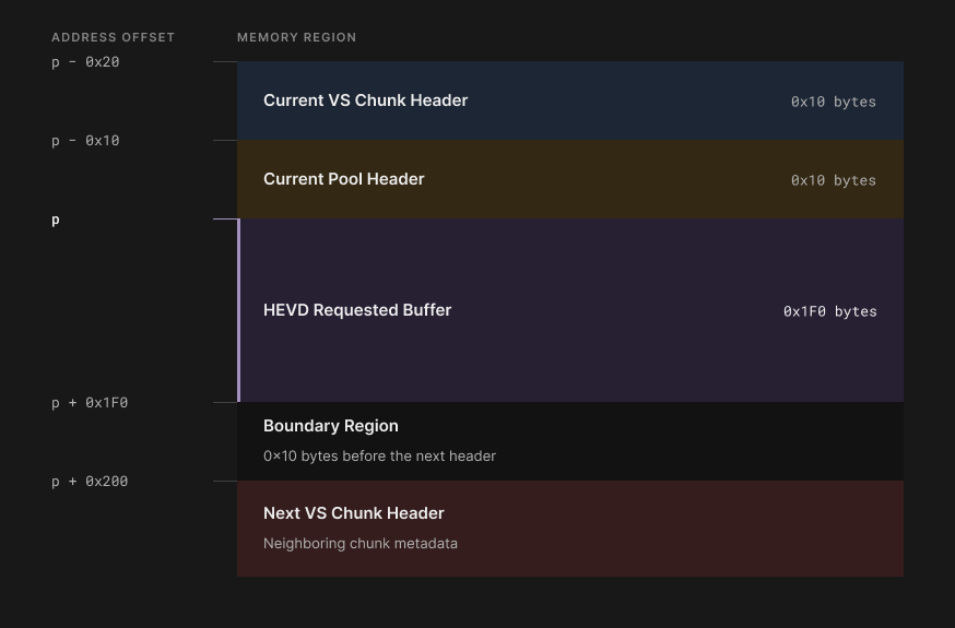
If we call the address of the allocated Pool P and inspect it in WinDbg, we can observe the result shown above. The Pool Header contains the Hack tag used for the allocation and BlockSize=0x20. On x64, the BlockSize field is expressed in units of 0x10 bytes. Thus, although the vulnerable kernel Pool itself was allocated with a requested size of 0x1F0, the Pool Header manages it as 0x200 bytes. Various references on Heap-backed Pool indicate that VS manages allocations starting at 0x200 bytes. This shows why we cannot assume that an allocation will necessarily be handled by LFH simply because the requested dynamic memory size is no greater than 0x200.
I also created a driver and tested this directly in a 25H2 environment. Even after repeating 0x1f0-byte Nonpaged Pool allocations more than 100 times, the requests continued to follow the VS Allocator path. In other words, because the Pool is recognized as 0x200 bytes from the outset, allocation takes the VS Allocator branch rather than the LFH Allocator branch.
In short, although HEVD requests 0x1F0 bytes of data, Windows 11’s Frontend Allocation adds 0x10 bytes when choosing the allocation path. The Pool Header therefore recognizes the Pool size as 0x200 and uses the VS Allocator.
4. Exploit
We have examined HEVD’s NX Nonpaged Pool Overflow vulnerability and the memory management structure of the VS Allocator. With that background, we can now analyze how a Pool Overflow affects Named Pipe objects and how the resulting behavior can be extended to Arbitrary Address Read/Write and privilege escalation.
The exploit proceeds in the following order:
- Pool Grooming
- Pool Overflow
- Named Pipe Metadata Corruption
- Arbitrary Address Read
- Arbitrary Address Write
- Token Swapping
- Cleanup
4.1 Pool Grooming
HEVD allocates 0x1F0 bytes of Nonpaged Pool. Even if a Buffer Overflow occurs, however, we do not know which object will be placed immediately after that buffer. We therefore need to prepare the Nonpaged Pool so that the objects we want to affect are already positioned where the overflow can reach them. In other words, the vulnerable object must be placed near our chosen objects.
Named Pipe is an object commonly used for exploits involving Nonpaged Pool. For more information about Named Pipe, please refer to the Hackyboiz article.
The Windows kernel’s NPFS (Named Pipe File System) manages data transferred through pipes in internal Queues, using structures such as NP_DATA_QUEUE_ENTRY. These DQEs are classified as Buffered Entries or Unbuffered Entries according to how they store data.
- Buffered DQE : the data follows immediately after the DQE Header.
- Unbuffered DQE : the data resides in
IRP->AssociatedIrp.SystemBuffer.
Let’s examine Pool Grooming using Buffered DQEs to allocate a vulnerable object in the desired memory region.
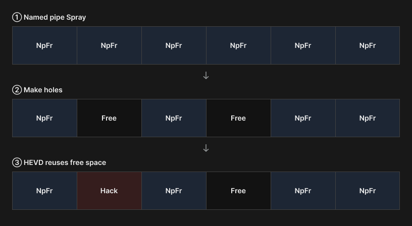
The diagram above shows the Pool Grooming sequence. First, we spray objects of the same size to create holes matching the size of the vulnerable object. A Buffered DQE has a Header size of 0x30 bytes. Therefore, writing 0x1C0 bytes of data to a Named Pipe produces a combined DQE Header and data size of 0x1F0 bytes. This matches the 0x1F0-byte allocation requested by HEVD.
After spraying Named Pipe objects in this way, we free selected objects among them to create holes. Freeing these objects changes the state of Free Chunks in VS. Once many Named Pipe objects have been allocated and some have been freed, the corresponding memory regions become available for reuse. This Pool Grooming increases the likelihood that HEVD’s vulnerable buffer will be allocated adjacent to a Named Pipe object.
4.2 Pool Overflow
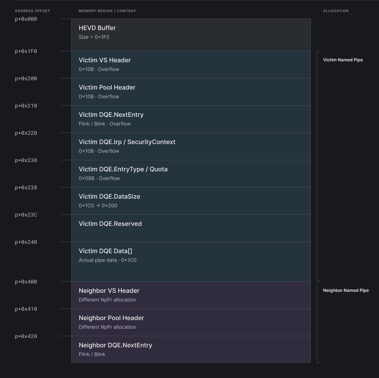
The vulnerability arises because RtlCopyMemory uses the separately provided InputBufferLength rather than the allocated buffer size of 0x1F0. For this exploit, we will set InputBufferLength to 0x23C, resulting in an overflow of 0x4C bytes.
Assuming Pool Grooming has placed the HEVD Buffer next to a Named Pipe object, the Buffer Overflow occurs in the memory layout shown below.
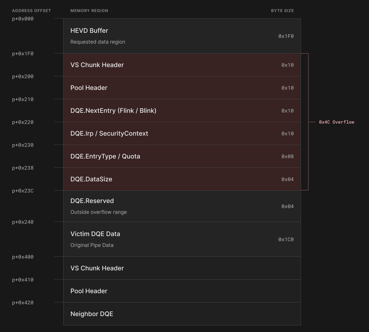
As shown in the layout above, an Overflow of 0x4C bytes can overwrite the DataSize field in the DQE Header. From now on, we will refer to the affected DQE as the Victim DQE.
4.3 Named Pipe Metadata Corruption
Following the Overflow, we can modify the Victim DQE Header, as shown in the memory diagram above. The Victim DQE Header’s original DataSize is 0x1C0; for the exploit, we will use the overflow to change its DataSize to 0x200. The DataSize field indicates the length of the data managed by that Queue Entry. If it is corrupted to a value larger than the actual stored data size, NPFS may access memory beyond the original data region while processing data according to the corrupted length. Calling PeekNamedPipe at this point allows the modified length to be read according to the DQE metadata, returning memory located beyond the original data.
PeekNamedPipe() is a Windows API that inspects data stored in a Named Pipe without consuming it. As in this example, if a DQE’s length metadata is corrupted, the Named Pipe object may copy memory beyond the actual data range.
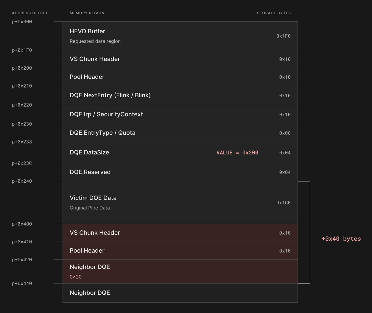
When the Victim DQE’s DataSize increases from 0x1C0 to 0x200, we can read 0x40 bytes beyond the original data region. The Neighbor DQE read in this process is the physically adjacent DQE, not the next Queue DQE linked through the Victim DQE’s NextEntry. At this stage, we can inspect the Neighbor DQE’s Header information, but we cannot yet implement AAR/AAW to read or write an arbitrary address.
4.4 Arbitrary Address Read (AAR)
What we obtained in the previous step is Information Disclosure: the ability to read 0x40 bytes beyond the Victim DQE’s data region. Now let’s extend this Information Disclosure into AAR so that we can read data from an address of our choosing.
There are two things we need to distinguish here:
- DQEs that are adjacent in a contiguous memory region
- The next DQE: the DQE pointed to by NextEntry
NPFS manages DQEs as a logical Queue, and a DQE’s NextEntry generally contains linkage information in the form of a LIST_ENTRY. In this structure, Flink points to the next Entry, while Blink points to the previous Entry. Importantly, the logical Queue order does not necessarily match the order of physical memory addresses. Therefore, a DQE adjacent in memory may be different from the DQE designated as the next Entry in the linked list.
Before proceeding, let’s look at how Named Pipe data is stored in the Queue and how PeekNamedPipe() works. As we saw earlier, this API reads and returns data based on the DQE metadata. If the requested amount of data exceeds the data available in the pipe, however, it reads the remaining bytes from the next DQE.
For example, suppose we call WriteFile() twice on a pipe, as shown below. WriteFile() is a Windows API used to write data to a specified pipe. Depending on the pipe state and buffering mode, NPFS may manage that data through internal DQEs. In this experiment, we use the path that creates Buffered DQEs.
WriteFile(pipe, "AAAA", 4, ...);
WriteFile(pipe, "BBBB", 4, ...);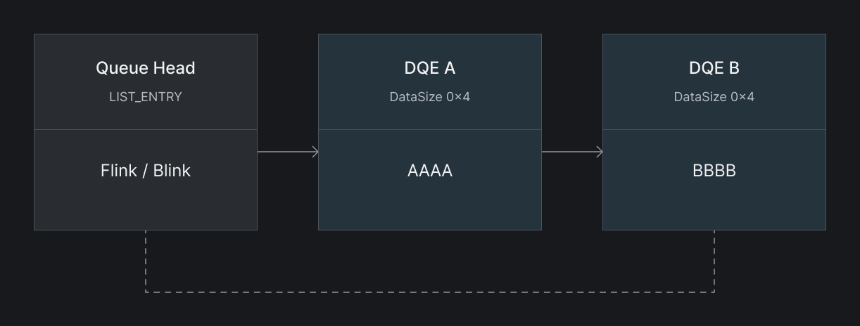
If we then request 8 bytes using PeekNamedPipe(), it first copies the 4 bytes from DQE A. Because 4 bytes of space remain in the output buffer, it moves to DQE B and copies those bytes into the buffer as well. As a result, PeekNamedPipe() returns AAAABBBB.
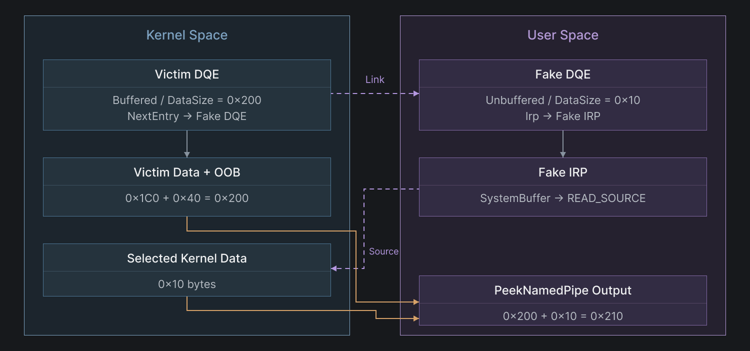
The Pool memory layout and structure after Information Disclosure has been established are shown below.
With this Pool layout, let’s proceed to the steps required to obtain AAR.
FakeDQE.EntryType = UNBUFFERED;
FakeDQE.Irp       = FakeIRP;
FakeDQE.DataSize  = READ_LENGTH;

FakeIRP.AssociatedIrp.SystemBuffer = READ_SOURCE;
By creating a Fake DQE and linking it to the Victim DQE.NextEntry, we can read from an arbitrary address. The Fake DQE is constructed with the same structure as a regular DQE, but it is configured as an Unbuffered DQE. We also create a Fake IRP and place the address of the data to be read in AssociatedIrp.SystemBuffer. This is how the DQE’s data is represented. We use an Unbuffered DQE because, instead of constructing a DQE that contains the data itself, we can handle the data more easily by changing only the address in IRP->AssociatedIrp.SystemBuffer.
uint8_t buffer[0x210]{};

BOOL ok = PeekNamedPipe(
    pipe, buffer, sizeof(buffer),
    &bytesRead, &available, nullptr
);

if (!ok || bytesRead != 0x210)
    return false;

uint64_t value = 0;
memcpy(&value, buffer + 0x200, sizeof(value));
Thus, when we call PeekNamedPipe() to read 0x210 bytes, the output buffer still has space after the 0x200 bytes specified by the Victim DQE’s DataSize have been read. The remaining 0x10 bytes are therefore read from the next DQE. In this case, those 0x10 bytes come from IRP->AssociatedIrp.SystemBuffer in the Fake IRP linked to the Fake DQE.
In other words, when the Overflow is triggered, manipulating the Victim DQE’s DataSize and NextEntry enables this process. The additional Fake DQE and Fake IRP then make it possible to read data from an address of our choosing.
4.5 Arbitrary Address Write (AAW)
In AAR, we read a value from a Named Pipe and returned it to a user buffer. For AAW, it helps to think of reversing the direction of data movement. Whereas AAR retrieves data from a Fake DQE, AAW involves writing data to a Fake DQE. To prepare for this, we need a Fake DQE and a Fake IRP containing the location information we want to manipulate.
First, we will use a Helper Pipe and Pending IRP handling to construct the Fake IRP.
During the preceding Overflow, the Victim Pipe’s DQE metadata and Queue linkage were corrupted. To examine the subsequent AAW process, we need additional objects separate from the original Victim Pipe. We therefore create another Named Pipe, which we will call the Helper Pipe. The Helper Pipe is used to prepare the IRP and related I/O state needed for AAW.
An IRP is a kernel object that handles I/O requests. If an additional Write request arrives when a pipe can no longer accept data immediately, the associated I/O request remains in the Pending state. In this exploit, we create a Buffered DQE containing 0x1C0 bytes of data in the Helper Pipe and request an Overlapped Write of 0x2000 bytes. This leaves the IRP for the 0x2000-byte Write in the Pending state. By keeping the request Pending, we can obtain the IRP associated with WriteFile(). Using AAR, we can read its structure, size, and management fields to reconstruct the IRP actually in use. We then pass this Fake IRP as the InputBuffer to NtFsControlFile().
NtFsControlFile() is a system service that sends FSCTL requests to a file system or file system filter. The exact I/O objects and Queue Entries created depend on the FSCTL used and the internal NPFS processing path. Here, we use the METHOD_BUFFERED method. In Windows Buffered I/O, the IRP’s AssociatedIrp.SystemBuffer represents the data. Consequently, passing the Fake IRP through InputBuffer produces a layout in which the Fake IRP we constructed resides in AssociatedIrp.SystemBuffer.
Although this may seem complicated, the key idea is to place the constructed Fake IRP in kernel memory. We use the information read from the Pending IRP through AAR as a template and modify the Inner IRP as needed. At this point, the modified data still resides in User Mode. It must be placed in kernel memory so that the Fake DQE can reference it later. NtFsControlFile() performs this step by copying the Fake IRP supplied through InputBuffer into AssociatedIrp.SystemBuffer in kernel memory. As a result, our Fake IRP now resides in kernel memory.
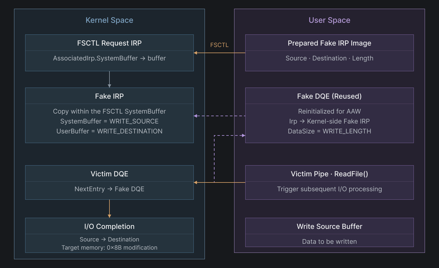
FakeIRP.AssociatedIrp.SystemBuffer = WRITE_SOURCE;
FakeIRP.UserBuffer = WRITE_DESTINATION;
FakeIRP.IoStatus.Information = WRITE_LENGTH;
We configure the Fake IRP for AAW as shown above. We then place it in kernel memory through the process described earlier. However, preparing the Fake IRP does not automatically cause the Victim Pipe to process it. To establish that connection, we reuse the Fake DQE from the AAR stage.
FakeDQE = RESET_DQE_STATE;
FakeDQE.Irp       = InnerIRP;
FakeDQE.DataSize  = WRITE_LENGTH;
When a read request is made to the Victim Pipe, NPFS processes data according to the data stored in the Queue and the state of the I/O request. During this process, the IRP is completed. If the IRP uses the Buffered I/O Completion path, the I/O Manager retrieves and processes data from AssociatedIrp.SystemBuffer.
// Pending IRP available
BOOL ok = ReadFile(
    victimPipe,
    &byte,
    1,
    &consumed,
    nullptr
);
The exploit performs AAW by using the data movement associated with ReadFile(). When ReadFile() is called, the manipulated Fake DQE and Fake IRP cause the source data indicated by AssociatedIrp.SystemBuffer to be written to UserBuffer.
4.6 Token Swapping
After obtaining the AAR and AAW primitives, we swap the EPROCESS.Token field.
Using AAR, we read the Tokens of the current process and the SYSTEM Process. We then use AAW to overwrite the current process’s Token, thereby obtaining SYSTEM privileges.
4.7 Cleanup
After the Overflow, the Victim DQE’s length information and Queue linkage may remain corrupted. If the pipe objects are freed or the Queue is cleaned up in this state, invalid memory references, metadata validation failures, or system crashes may occur. Therefore, after the exploit, we need to inspect the corrupted metadata and related I/O state and restore the consistency of the data structures wherever possible.
For normal Free operations and Queue cleanup, the Allocator Metadata and the Named Pipe linkage must be consistent. After completing Token Swapping through AAR and AAW, we restore the information that we modified to its original state. This step is necessary to prevent a BSOD after EoP.
5. Conclusion
In this article, we examined the basic Allocation structure of Windows Kernel Pool and the operation of the VS Allocator, then explained Kernel Exploitation using HEVD’s Nonpaged Pool Overflow vulnerability. It was also a valuable opportunity for me to learn more about Windows Kernel Pool.
Kernel Pool continues to evolve and change, so results may differ depending on the environment and Windows version. Please keep your own environment in mind when considering these findings.
Thank you for reading this article!
Reference
- Windows Internals
- Inside Your Kernel — HEVD Nonpaged Pool Overflow
- Tarjei Mandt — Kernel Pool Exploitation on Windows 7
- Mark Vincent Yason — Windows 10 Segment Heap Internals
- Bayet & Fariello — Pool Overflow Exploitation Since Windows 10 19H1
- Yarden Shafir et al. — Windows Heap-Backed Pool
- Angelboy — Windows Kernel Heap: Segment Heap in Windows Kernel Part 1
- Rotce — Windows Kernel Heap Internals
- Kernullist — About Kernel Segment Heap
- Microsoft — ExAllocatePool2
- Microsoft — POOL_FLAGS
- HEVD — HackSys Extreme Vulnerable Driver

본 글은 CC BY-SA 4.0 라이선스로 배포됩니다. 공유 또는 변경 시 반드시 출처를 남겨주시기 바랍니다.